Welcome to the Phototiler documentation! Phototiler is a 3D tool that can be used to make high quality map rendering and export 3D models in a minimalistic interface.
If you've ever felt overwhelmed using Blender's interface or other generic 3D software not dedicated to maps, Phototiler can be the right tool for you.
Its minimal design aims to have a low cognitive load interface, while taking advantage of advanced rendering techniques that can't be achieved in real-time rendering of maps. It is built natively for Linux, macOS and Windows to take best advantage of your computer's hardware, for a fast 3D model generation process.
For any question about the software, feel free reach out to phototiler@gmail.com.
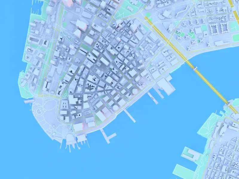
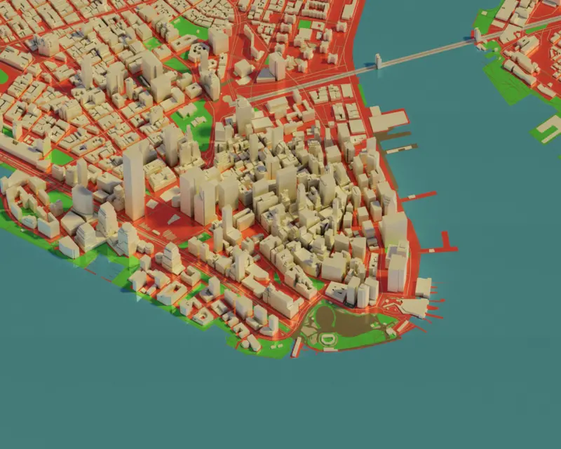
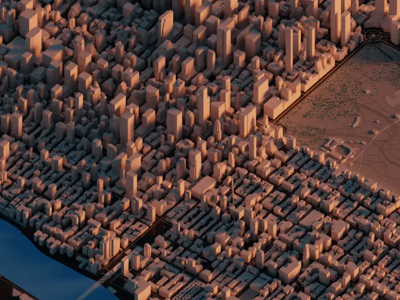
Phototiler has two main features; generation of 3D map models taken from real-world data and photorealistic rendering of maps for static cartography. The data can be sourced from different data providers, such as Nextzen and Mapbox, it is then processed and filtered with a user-defined style to create a 3D model of the map.
The 3D models can be exported as GLTF files, which can be used in Blender, Unity, Unreal Engine, Sketchfab or other CAD and general purpose 3D software.
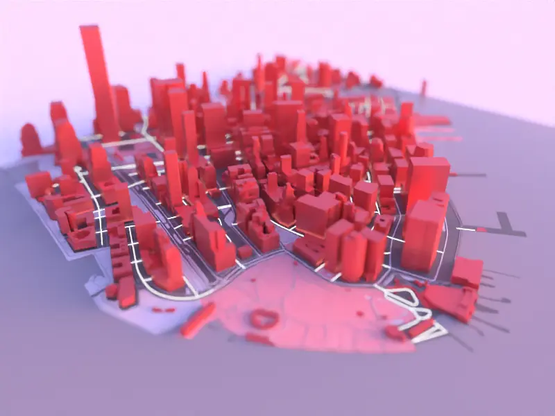
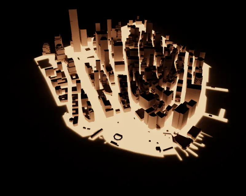
The rendering is done using a path tracer, which is a type of global illumination algorithm that can produce highly realistic images and accurate lighting effects. Once finalized, the renders can be exported as PNG images, which can be further edited in any image editing software or directly used as is.
To speed up the rendering process, Phototiler has a built-in AI-based denoiser. This denoiser is able to remove noise from the rendered images while preserving the important details and features of the image for clean and smooth results.
Phototiler is available for non-commercial and evaluation purposes. If you are interested in using Phototiler for commercial purposes, you can get a commercial license by purchasing a license key.
Phototiler evaluation has no time limit. If the evaluation demo is all you need, feel free to use forever :)
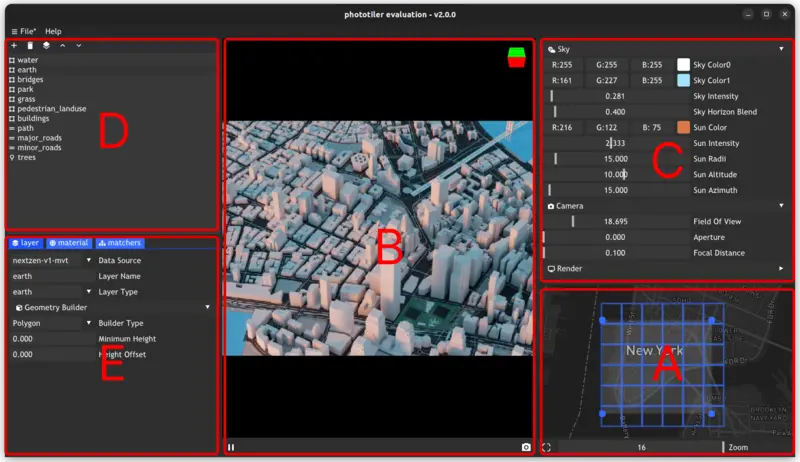
The interface is divided into 5 main sections.
The first part of the user interface you might use is the map region selection. Located at the bottom right of the interface, you can use it to select a region of the map to render or export by clicking and dragging on the blue dots of the map area.
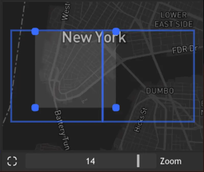
You can also use the zoom control at the bottom to increase or decrease the map level of detail. Increasing the level of detail will result in more tiles being downloaded and rendered, which can increase the complexity of the scene and rendering time. On this view, the tiles are represented by blue squares.
At the bottom left of the map selection, the crop button will allow you to recenter the selection on the currently viewed area.
As soon as you make changes to the map region selection, the data will be downloaded and 3D model updated to reflect the changes.
To render an image, Phototiler uses a rendering algorithm called path tracing. This is a Monte Carlo rendering technique used to create photorealistic images of 3D scenes. It works by tracing the paths of light rays from the camera through the scene and simulating the interactions of the rays with the objects in the scene.
Using a global illumination algorithm means that it accounts for the indirect illumination of objects in the scene. This is in contrast to local illumination algorithms, which only consider the direct illumination of objects from light sources and what is typically used in real-time map rendering.
Path tracing works by sampling the light rays that are emitted from the camera and following them through the scene. At each point where the light ray intersects an object in the scene, the algorithm calculates the amount of light that is absorbed, scattered, or reflected by the object. This information is used to update the color and intensity of the light ray, and the ray is then traced further through the scene.
After a large number of light rays have been traced through the scene, the algorithm calculates the color of each pixel in the image by averaging the colors of the rays that pass through that pixel. This produces a high-quality, photorealistic image of the scene. It is a computationally intensive rendering technique, but it is able to produce very realistic images with complex lighting and shadow effects. In Phototiler, this algorithm is implemented on the GPU.
You can monitor rendering at the center of the interface, in the rendering viewport. The blue progress bar at the bottom displays the rendering progress, determined by the total number of samples chosen for the image. The more samples, the more accurate the rendering will be, but the longer it will take to render. Once the rendering has reached the desired number of samples, the denoiser will get applied and remove the noise from the image.
At the top right of the rendering viewport, you can find a small camera control, which allows you to orbit the camera along the principal axis of the scene. You can also use the mouse to scroll, pan and zoom in and out of the scene. The camera controls are described below.
| Control | Description |
|---|---|
| Right Mouse Click + Mouse Drag | Control camera orbit |
| Shift + Right Mouse Click + Mouse Drag | Control camera translation |
| Mouse Scroll | Camera zoom in and out |
On the bottom right, you can use the camera icon to export the render as a PNG image, and the play and pause icons to start and pause the rendering process.
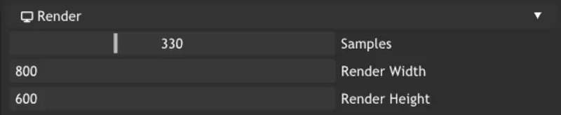
On the right side of the interface, you can find the application settings. This tab allows you to configure the number of samples and the rendering resolution. The higher the number of samples, the more accurate the rendering will be, but the longer it will take to render. The resolution will determine the size of the final image, it is only available for Phototiler Pro.
The camera settings tab allows you to configure the camera field of view, aperture and focal distance.
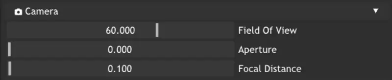
The camera field of view (FOV) is the angle of view covered by the lens of a camera. It is the angle between the two lines of sight that define the edges of the image sensor. The camera FOV determines the amount of the scene that is captured.
The camera FOV is an important consideration in photography and video, as it determines the perspective of the image. A wide-angle FOV will capture a broader view of the scene, while a narrow FOV will capture a more zoomed-in view. For example, a narrow-angle FOV can be used to make orthographic projections. The choice of FOV will depend on the intended use of the image and the desired visual effect.
The camera aperture is the opening in the lens that allows light to pass through to the image sensor. The size of the aperture is measured in f-stops, which are a ratio of the focal length of the lens to the diameter of the aperture. A smaller f-stop number indicates a larger aperture, while a larger f-stop number indicates a smaller aperture.
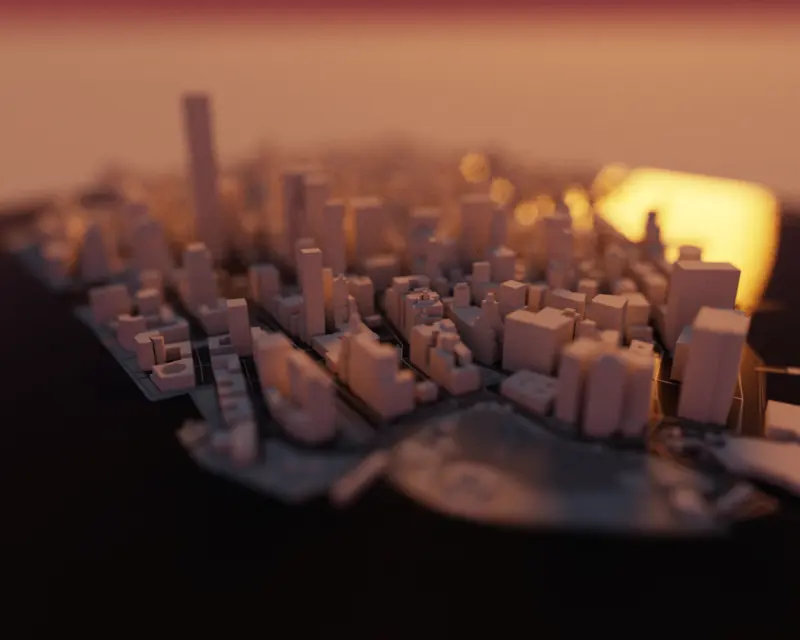
The camera aperture is an important consideration in photography and video, as it determines the depth of field of the image. A wide aperture will produce a shallow depth of field, while a narrow aperture will produce a deep depth of field. The choice of aperture will depend on the desired visual effect.
The sky settings control the environment lighting. It is split into two main components, the sky and the sun, each of which acts as an infinite light source.
To control the environment lighting you have the following settings:
sky color 0 an RGB value that controls the first color of the sky, which blends starting at the bottom of the horizon linesky color 1 an RGB value that controls second the color of the sky, which blends above the first sky color starting from the horizon linesky intensity the intensity of the sky light sourcesky horizon blend controls where the blend between sky color 0 and sky color 1 should occur, lower values mean the blend between the two sky colors will be closer to the horizon linesun color an RGB value that controls the color of the sun disksun intensity the intensity of the sun light sourcesun radii the radius of the sun disk, in degrees. Adjusting the sun radius affects the look of shadows, where a smaller radius leads to sharp shadows, compared to bigger radius that leads to soft shadows.sun altitude the altitude angle of the sun disk, relative to the horizon line. Between -90 and 90, where 90 is at the zenithsun azimuth the azimuth of the sun disk. In degrees, ranging between 0 and 360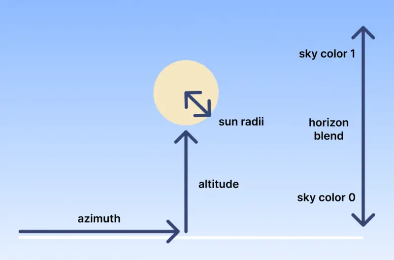
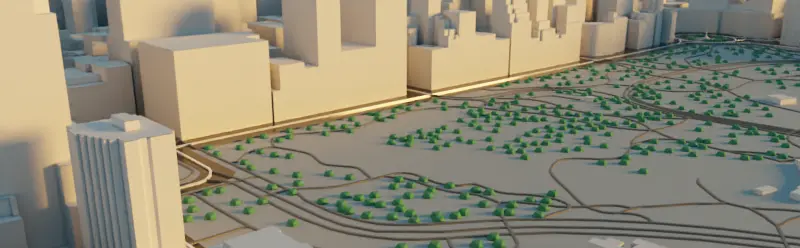
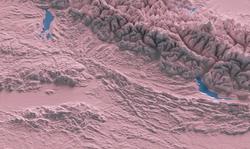
Since phototiler v2.2.0, you can use terrain to elevate your layers. To enable terrain, simply increase the extrusion value to be above 0 in the settings panel. You can also choose to include a base mesh, and provide a material for it.
For all layers that are in the scene, phototiler processing will subdivide and clip the layer polygons against the terrain geometry grid patches in order to properly match and fit the extruded terrain geometry. This allows to have layer geometry morph against the terrain geometry.
In the context of mapping, a map layer is a separate and distinct collection of data that is displayed on a map. A map may have multiple layers, each representing a different type of data or a different aspect of the map.
Map layers are used to organize and display complex spatial data in a way that is easy to understand and analyze. Each layer typically represents a different theme or category of data, such as roads, buildings, rivers, or land use. By overlaying multiple layers on top of each other, users can create maps that show a rich and detailed view of the area being mapped.
For 3D mapping, map layers can be extruded to create 3D buildings, roads, and other features to give a sense of perspective. But the underlying data source layer is still organized in 2 dimensions. In Phototiler, you provide styling rules for each layer so that it can be processed, tesselated and extruded into a 3D model.
Each layer has its own data source. Currently, Phototiler supports two different data source endpoints:
For now, these data sources can't be modified, but control over data source endpoints may be added in future versions.
To style a map, knowledge of the underlying data source may be needed so the documentation of each of these data endpoint might become handy.
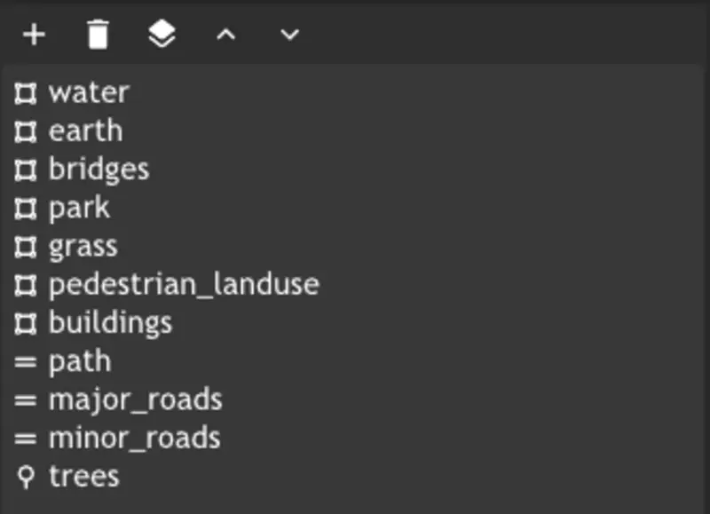
The layer order defines visual ordering on the axis going upward from the ground. It is applied as a small epsilon offset on the geometry between layers with a separate order. Layer order is implicitly defined by the order in which they appear in the layer list and can be switched by the arrow up and arrow down buttons.
For example, if you want to display a land-use layer and a park layer, since the land-use layer will include the park layer footprint, you might want to put the park layer above the land-use layer to properly display it.
Phototiler currently supports 3 types of geometry builders: Polygon, Line and Point. Each of these builders can be applied independently to the geometry of a layer. For example, you can have a layer containing polygons and apply the point builder to display points at each polygon edge, or the line builder to display a line at each polygon edge. To display buildings, you can use the polygon builder with a given height to extrude the polygons into 3D buildings.
Sometimes, the underlying data source may not have height information. In that case, you can use the polygon builder minimum height value to assign a given height to each polygon.
A map layer filter is a tool used to selectively display or hide data in a map layer. Map layer filters allow users to focus on specific aspects of the data in a layer, or to exclude irrelevant or uninteresting data from the map.
Map layer filters are applied using a set of rules or criteria that define which data should be displayed and which data should be hidden. These rules can be based on the attributes of the data, such as the type, category, or value of the data.
Phototiler currently supports three types of filter, which can be combined for a single layer:
To create a filter, navigate to the filter tab, select the category of filter you want to create between any of, all of, none of, select the operator type of your filter and click on the + button.
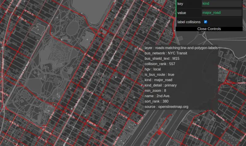
Equals checks if the value of the layer property is equal to the value of the filterIsTrue checks if the value of the layer property is trueExists checks if the value of the layer property existsRange checks if the value of the layer property is within (inclusive) the range of the filterRangeMin checks if the value of the layer property is greater than or equal to the minimum value of the filterRangeMax checks if the value of the layer property is less than or equal to the maximum value of the filterRegex checks if the value of the layer property matches the regular expression of the filterInspecting the data can be useful to create filters and style the map. For each of the data source, you can inspect the data with the following inspectors:
In 3D graphics, a material is a set of properties that define the appearance of an object's surface. These properties can include the color, texture, transparency, reflectivity, and other optical characteristics of the object.
Materials are often used in 3D graphics to add realism to a scene. They allow objects to have different surface properties, such as the metallic shine of a car's body or the rough texture of a stone wall. This makes the objects in the scene look more realistic and believable.
Phototiler uses the metallic roughness shading model. It is a shading model that is used to define the appearance of materials with metallic and rough surfaces. The model is based on the idea that metallic materials have a specular reflectance that depends on the roughness of the surface, and that rough surfaces scatter light in a diffuse manner. Each layer can have its own material, which can be configured in the layer view.
In the metallic roughness model, the reflectivity of a material is controlled by two parameters: the metallic value and the roughness value. The metallic value determines the amount of light that is reflected from the surface in a specular manner, while the roughness value determines the amount of light that is scattered in a diffuse manner. These values can be adjusted to create a wide range of different materials, from highly reflective metals to rough, matte surfaces.
Materials also have the possibility to be emissive. When using the emission entry of the material parameters, the geometry becomes a light source and will emit lights to its surrounding based on its material color. Note that when you use emission, the metallic and roughness parameters are not used.
| Shortcut | Description |
|---|---|
| Ctrl+N | Create a new scene |
| Ctrl+O | Open an existing scene file |
| Ctrl+S | Save the currently opened scene file |
| Ctrl+Shift+S | Save the currently opened scene as a new file |
| Ctrl+Shift+E | Export the currently opened and generated scene as a GLTF 3D model |
| Ctrl+E | Export the current render as a PNG image |